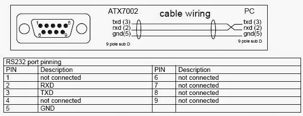
The RS232 protocol has been around for many years now. There are various versions and we have to be aware that non-standard applications are used often. The main aspects are the sockets and plugs and the packet sending rules.
Monday, March 31, 2014
Monday, March 24, 2014
Think about your wearable project
The next project is about using an embedded system very close to a person. It could be on clothes, shoes or on something you carry or on an accessory like a coat, hat or belt. Some ideas below are given in links.
Links
http://atmelcorporation.wordpress.com/2014/01/23/wearables-to-create-personal-data-streams/?utm_campaign=January_2014_Newsletter.html&utm_medium=email&utm_source=Eloqua
http://www.instructables.com/id/Despicable-Me-Minion-Costume-1/
http://learn.adafruit.com/light-activated-pixel-heart
http://www.nst.com.my/life-times/tech/top-picks-ground-breaking-wearable-gadgets-1.528292
http://realbusiness.co.uk/article/26128-7-of-the-best-tech-gadgets-from-londons-wearable-technology-show
http://www.pcadvisor.co.uk/news/google-android/3507296/android-wear-release-date-smartwatches/?cmpid=HTML-DN190314&olo=daily%20news
http://sensoree.com/
Monday, March 17, 2014
First sensor: the LDR

Some good code and information here.
Light dependent resistor circuit. See http://www.ladyada.net/learn/sensors/cds.html
Light dependent resistor circuit. See http://www.ladyada.net/learn/sensors/cds.html
Some voltage divider images
We often want a sensor to send its signal using a changing voltage. For instance when the temperature is high we get a big voltage, and when the temperature is low we get a low voltage. Note that normally the input to an Arduino analog pin has to be between 0 and 5 volts.
Monday, March 10, 2014
Monday, March 3, 2014
Running two LEDs
/*
Blink2
Turns on a LED on for half a second, then off for half a second, repeatedly. It also does the same to an off-board LED connected to pin 12 so that when one LED is on the other is off.
The circuit:
* LED connected from digital pin 13 to ground via resistor.
* second LED connected from digital pin 12 to ground via resistor. I used 330 ohms.
* Note: On most Arduino boards, there is already an LED on the board
connected to pin 13.
Created 1 June 2005
By David Cuartielles. Adapted by Peter Brook
based on an orginal by H. Barragan for the Wiring i/o board
*/
int ledPin = 13; // LED connected to digital pin 13
int redLedPin = 12; // LED connected to digital pin 13
int del =500;
// The setup() method runs once, when the sketch starts
void setup() {
// initialize the digital pin as an output:
pinMode(ledPin, OUTPUT);
pinMode(redLedPin, OUTPUT);
}
// the loop() method runs over and over again,
// as long as the Arduino has power
void loop()
{
digitalWrite(ledPin, HIGH); // set the LED on
digitalWrite(redLedPin, LOW); // set the LED on
delay(del); // wait
digitalWrite(ledPin, LOW); // set the LED off
digitalWrite(redLedPin, HIGH); // set the LED on
delay(del); // wait
}
Blink
Turns on an LED on for one second, then off for one second, repeatedly.
The circuit:
* LED connected from digital pin 13 to ground.
* Note: On most Arduino boards, there is already an LED on the board
connected to pin 13, so you don't need any extra components for this example.
Created 1 June 2005
By David Cuartielles
http://arduino.cc/en/Tutorial/Blink
based on an orginal by H. Barragan for the Wiring i/o board
*/
int ledPin = 13; // LED connected to digital pin 13
// The setup() method runs once, when the sketch starts
void setup() {
// initialize the digital pin as an output:
pinMode(ledPin, OUTPUT);
}
// the loop() method runs over and over again,
// as long as the Arduino has power
void loop()
{
digitalWrite(ledPin, HIGH); // set the LED on
delay(1000); // wait for a second
digitalWrite(ledPin, LOW); // set the LED off
delay(1000); // wait for a second
}
Subscribe to:
Posts (Atom)


