Wednesday, June 4, 2014

What's in the theory test

A outline of what's in the test.

The test will be in our normal classroom on Thursday 12th June at 3:13pm

There will be a picture of an Arduino like this but red and you'll annotate it with text and arrows.

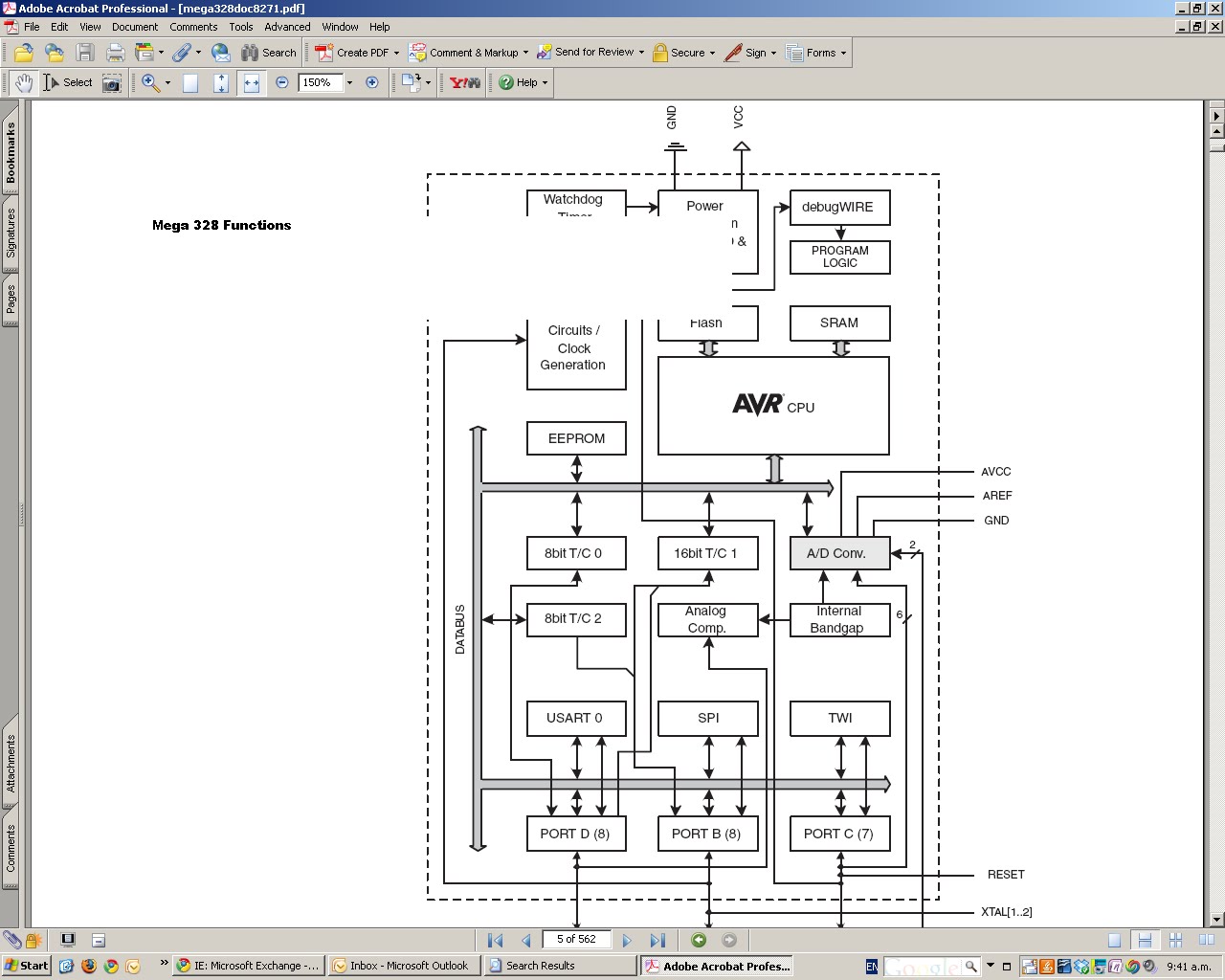
There will be one of the two pages from the Atmel mega 328 family's data pdf. You'll be required to comment on some of the functions in the page below and most of the features in the very front page.


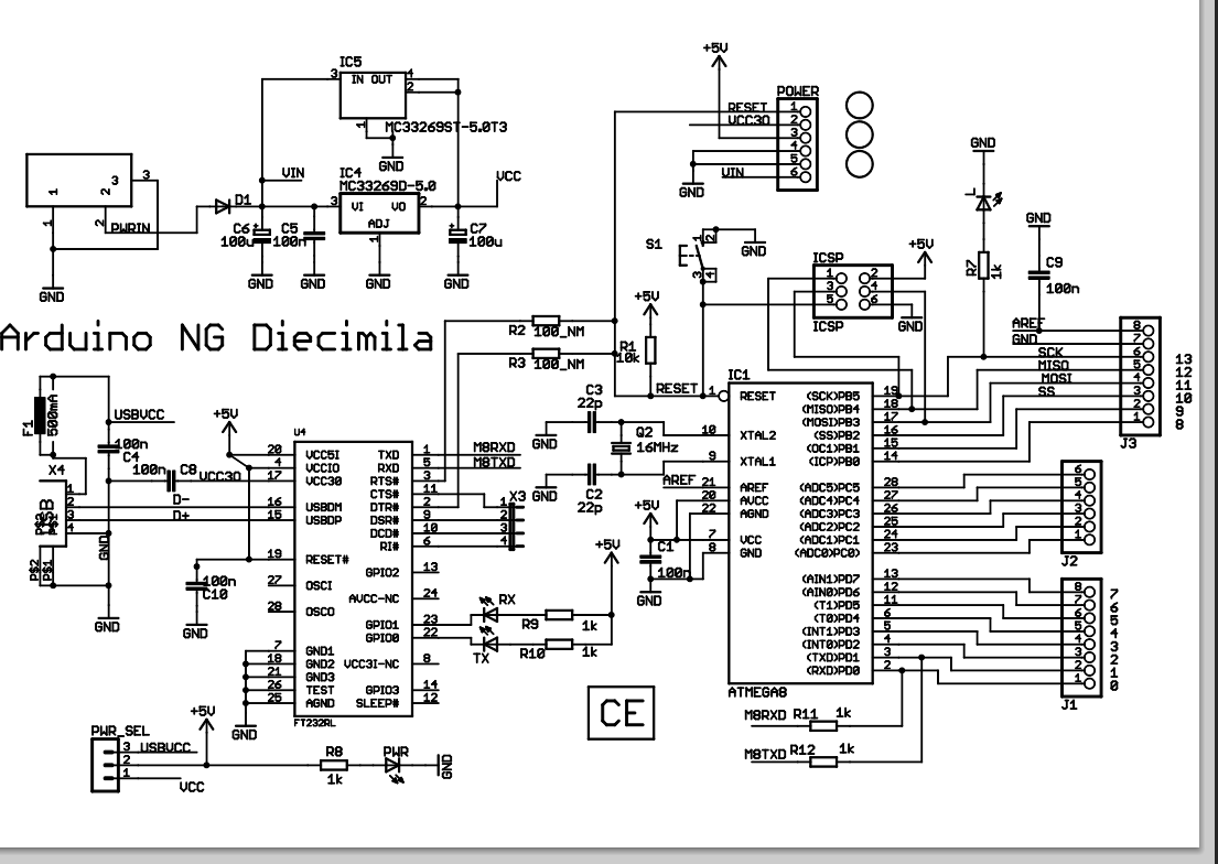
There will be questions about a schematic involving the Arduino like the one below.

Test Information

There will be a theory test on Thursday 12 June. It will be closed book and you must complete it in 1 hour and 45 minutes. We will discuss some of the items in the test, the previous class.

There will be a question on the main parts of the Arduino. See the labelled diagram above. This is not exactly the same as our Arduino but, apart from the DIL processor and colour, is pretty close.

There will be a question on the page above called The Front Page of the Mega328. You will be expected to write a sentence explaining some of the features listed. 

There will be questions on the functions diagram of the Mega328. You will be given a copy of this diagram and be expected to write a short paragraph on up to three blocks.

There will be a question about the Arduino schematic diagram above or similar.

Also there's buggy program. A program will be given to you with errors in it. You will have to identify the errors. Mostly syntax violations.

A problem to do with sampling real world inputs will be given and you will be asked how you would respond to this using the Arduino.

You will be asked to write a simple assembly language program. You will be asked to write a program in Arduino C.

There may be other questions but only on items we have studied in class including serial buses, pin outs of the Arduino and the mega328p, voltage dividers, the stack and interrupts. A simple question on using timers may be asked.

Please contact me about any problems. Good luck.

PeterB


i2c two wire bus

Most popular of the serial buses. Uses one wire for clock and one wire for bidirectional data. Based on Phillips' iic network. Lots of chips use the i2c protocol.

Good short introduction here. Not Arduino based.

Using i2c to connect arduino to eeprom chip that holds 256k bits, here.


SPI Bus

Fastest of the serial I/O on the Arduino.

A good tutorial on spi using a digital potentiometer chip here

A tutorial on the spi bus, more technical here

Two Arduino's connected via spi here. Code via link to github.


Monday, June 2, 2014

AVR Interrupts


Some interesting sites:

General AVR Interrupt using GCC here
Arduino simple interrupt Click here

Not a bad video here

Redboard and schematic

Schematic diagram for our Redboard Arduino


Above: The Sparkfun Red Board Arduino. Link to it here.

Monday, May 26, 2014

You need to set up the stack before using calls and interrupts using assembler

The code for the above program is:

.include "m328pdef.inc"
main: ;set up the stack
ldi r16, low(RAMEND)
out SPL, r16
ldi r16, high(RAMEND)
out SPH, r16
nop call below
finish: rjmp finish
below:
ldi r17,$99
ret

The relevant part of the def.inc file the shows what RAMEND is for this processor is:

; ***** CPU REGISTER DEFINITIONS *****************************************
.def XH = r27
.def XL = r26
.def YH = r29
.def YL = r28
.def ZH = r31
.def ZL = r30


; ***** DATA MEMORY DECLARATIONS *****************************************
.equ FLASHEND = 0x3fff ; Note: Word address
.equ IOEND = 0x00ff
.equ SRAM_START = 0x0100
.equ SRAM_SIZE = 2048
.equ RAMEND = 0x08ff
.equ XRAMEND = 0x0000
.equ E2END = 0x03ff
.equ EEPROMEND = 0x03ff
.equ EEADRBITS = 10
#pragma AVRPART MEMORY PROG_FLASH 32768
#pragma AVRPART MEMORY EEPROM 1024
#pragma AVRPART MEMORY INT_SRAM SIZE 2048
#pragma AVRPART MEMORY INT_SRAM START_ADDR 0x100


; ***** BOOTLOADER DECLARATIONS ******************************************
.equ NRWW_START_ADDR = 0x3800
.equ NRWW_STOP_ADDR = 0x3fff
.equ RWW_START_ADDR = 0x0
.equ RWW_STOP_ADDR = 0x37ff
.equ PAGESIZE = 64
.equ FIRSTBOOTSTART = 0x3f00

Thursday, May 22, 2014

Writing hex files directly to an Arduino

Programs needed are just AVR Studio and avrdude. I used AVR Studio version 4.14 and the avrdude that came with the Arduino suite.

Step 1. Write your program in assembler in AVR Studio, build then save the hex file.
Step 2. Go into the command prompt and invoke avrdude with the right switches.

I started with the usual Arduino C blink program, just to make sure I got the COM port right and to see the hardware was all working. Then did steps above.

Below are some relevant screen shots.


Blink for AVR Studio 4 assembler


.include "m328pdef.inc"


;Based on http://www.robertoinzerillo.com/wordpress/?p=5
;-----------------------------------------;
; FIRST WE'LL DEFINE SOME REGISTER TO USE ;
;-----------------------------------------;
.DEF A = R16   ;GENERAL PURPOSE ACCUMULATOR
.DEF I = R21   ;INDEXES FOR LOOP CONTROL

.ORG $0000

;-----------------------------------------;
; FIRST WE SETUP A STACK AREA THEN SET    ;
; DIRECTION BIT ON PORT-B FOR OUTPUT/SPKR ;
;-----------------------------------------;
START:
  LDI A,LOW(RAMEND)   ;SETUP STACK POINTER
  OUT SPL,A           ;SO CALLS TO SUBROUTINES
  LDI A,HIGH(RAMEND)  ;SETUP STACK POINTER
  OUT SPH,A           ;SO CALLS TO SUBROUTINES

  LDI A,0b1111_1111   ;SET ALL PORTB FOR OUTPUT
  OUT DDRB,A          ;WRITE 1s TO DIRECTN REGS

;--------------;
; MAIN ROUTINE ;
;--------------;
LEDONOFF:
  SER A
  OUT  PORTB,A
   RCALL DELAYLONG
  CLR A
  OUT PORTB,A
   RCALL DELAYLONG
  RJMP LEDONOFF
 

DELAYLONG:
; =============================
; Delaying approximately 1 sec at 8Mhz.
; This code has been created with  “AVR Delay Loop Generator V1.2?.
          ldi  R17, $48
WGLOOP0:  ldi  R18, $BC
WGLOOP1:  ldi  R19, $C4
WGLOOP2:  dec  R19
          brne WGLOOP2
          dec  R18
          brne WGLOOP1
          dec  R17
          brne WGLOOP0
; =============================
RET


Wednesday, May 14, 2014

Delays in assembler and some tasks.

We often need to introduce a small delay into our programs. We often do this decrementing  or incrementing a register until it becomes a zero.

.include "m328pdef.inc"
ldi r16,1
ldi r17,1
call delay
here: nop
rjmp here
delay:
inc r16
brne delay
;rjmp here
ret

-----------------------------------some tasks----------------------------------------------
;helpful code. See below
.include "m328pdef.inc"
startprog: nop
up1:inc r5
brne up1
nop
nop
nop
inc r6
brne up1
end: rjmp end

Write short code segments in AVR Studio 4 to do the following. Put the code into your blog. Also add the relevant part of

the list file. Say how many cycles at 16MHz your segemnt used.

1) Put $16 into r16 and $17 into r17.
2) Put $11 in r11 and $12 into r12.
3) The above program takes over 49ms to get to the end: label. Say exactly how many micro-seconds.
4) Tweak number 3 above to take exactly 50ms.
5) In the Arduino we have a delay() for so many milli-seconds. Write a segment to delay r0 milli seconds. For instance if r0 contained 50 the delay would be 50ms.
6) Repeat number 4 but use dec instead of inc.
7) Write a segment to swap the contents of r0 and r1.Use specific numbers that you chose for contents.
8) Write a segment to reverse the order of the contents in r0,r1 and r2.
9) Replace any $01 in r0,r1,r2 with $ff. (Hint. Dec and check Z flag with brne or breq.)
10) Using inc, increment r0 as many times as the number in r1. Eg if r0=3 and r1= 4, then r0 would become 7.

Monday, May 5, 2014

Monday, March 31, 2014

RS232 protocol

The RS232 protocol has been around for many years now. There are various versions and we have to be aware that non-standard applications are used often. The main aspects are the sockets and plugs and the packet sending rules.


Monday, March 17, 2014

First sensor: the LDR


Some good code and information here.
Light dependent resistor circuit. See http://www.ladyada.net/learn/sensors/cds.html


Some voltage divider images

We often want a sensor to send its signal using a changing voltage. For instance when the temperature is high we get a big voltage, and when the temperature is low we get a low voltage. Note that normally the input to an Arduino analog pin has to be between 0 and 5 volts.


Monday, March 3, 2014

Running two LEDs

/*
Blink2
Turns on a LED on for half a second, then off for half a second, repeatedly. It also does the same to an off-board LED connected to pin 12 so that when one LED is on the other is off.
The circuit:
* LED connected from digital pin 13 to ground via resistor.
* second LED connected from digital pin 12 to ground via resistor. I used 330 ohms.
* Note: On most Arduino boards, there is already an LED on the board
connected to pin 13.
Created 1 June 2005
By David Cuartielles. Adapted by Peter Brook
based on an orginal by H. Barragan for the Wiring i/o board
*/
int ledPin = 13; // LED connected to digital pin 13
int redLedPin = 12; // LED connected to digital pin 13
int del =500;
// The setup() method runs once, when the sketch starts
void setup() {
// initialize the digital pin as an output:
pinMode(ledPin, OUTPUT);
pinMode(redLedPin, OUTPUT);
}
// the loop() method runs over and over again,
// as long as the Arduino has power
void loop()
{
digitalWrite(ledPin, HIGH); // set the LED on
digitalWrite(redLedPin, LOW); // set the LED on
delay(del); // wait
digitalWrite(ledPin, LOW); // set the LED off
digitalWrite(redLedPin, HIGH); // set the LED on
delay(del); // wait
}
 Blink

 Turns on an LED on for one second, then off for one second, repeatedly.

 The circuit:
 * LED connected from digital pin 13 to ground.

 * Note: On most Arduino boards, there is already an LED on the board
 connected to pin 13, so you don't need any extra components for this example.


 Created 1 June 2005
 By David Cuartielles

 http://arduino.cc/en/Tutorial/Blink

 based on an orginal by H. Barragan for the Wiring i/o board

 */
int ledPin =  13;    // LED connected to digital pin 13
// The setup() method runs once, when the sketch starts
void setup()   {              
 // initialize the digital pin as an output:
 pinMode(ledPin, OUTPUT);   
}
// the loop() method runs over and over again,
// as long as the Arduino has power
void loop()                   
{
 digitalWrite(ledPin, HIGH);   // set the LED on
 delay(1000);                  // wait for a second
 digitalWrite(ledPin, LOW);    // set the LED off
 delay(1000);                  // wait for a second
}

Monday, February 24, 2014

Check list for first two weeks

Make sure you have addressed the following topics.

Week one
Access class Moodle site.
Access class blog.
Created own blog.
Put blog URL into Moodle wiki.
Started tasks from class blog.
Purchased Arduino kit.
Unpacked kit and got default led flash after plug in.

Week two
Get Arduino IDE going.
Look at main Arduino site.
Checked pages on how to get started.
Found example programs in IDE.
Run famous Blink Program.
Did simple mods to Blink and ran them.
Understand structure of Arduino sketch.
Found the Arduino C language reference.
Installed kit's project software in examples.
Do blink sketch from kit book.
Download Fritzing.
Accessed specs for LED project.
Continued with blog tasks.


Sunday, February 16, 2014

List of Tasks. You have to respond to all of these in your blog.
Please number your tasks in your blog so they can be found easily.


1. Start your blog.

2. Edit the permissions in your blog so that just prjbrook@gmail.com is invited to see it.

3. Make sure you can access the Arduino environment. Find the Blink program in the examples and paste into your blog. Test that it compiles in the Arduino IDE but you don't have to send it to your Arduino yet.

4. What is the name of the Atmel microprocessor in your Arduino board? Insert the link to the large pdf from Atmel associated with this chip. Insert an image of the first page of this pdf. Finally insert a picture of the pin-out of this chip.

5. Find the forum associated with main Arduino site. Take a screen shot of something in the forum that interests you with a comment on what appeals to you.

6. Find a picture of your Arduino  publish it in your blog and label the main parts. You may need a special graphics program to do this. Add another interesting Arduino variation. You can see some on this page.

7. Put the url for your blog into the wiki in Moodle. Add some other contact details. If you wish to remain private that's OK too.

8. Check out the following sites. Insert a screen shot and a URL link into your blog. Small images or large ones are both OK .
The Arduino environment version 1.0.
The Processing environment.
The Fritzing files.
Link to Blogger.
GNU gcc
Moodle
AVR Studio download. Latest version.
PDF of ATMega 328
PDF of specs of USB-to_serial chip. The one used in the Duemilanove.
Good pic of our arduino clone
The MindKits site.
One cool video on Youtube.
One other interesting internet resources. eg "Make" site or electonics sites.
The Nice Gear store in Timaru that sells good Arduinos.

9. Find 4 more Arduino LED related videos in Youtube, BlipTV etc. Put a link and a two-sentence review about each one in your blog. Be prepared to talk about one or more of them to the class.

10. Establish a sketchpad folder in the D Drive or in a USB pen or somewhere you can get to.


The next tasks will relate to programming your Arduino using the Blink program with variations. So you might like to get going on setting things up.

All programs from now on need their source code to be entered into your blog with comments. Make sure you comment the the top of your blog posting with the number of the task and enter too the task number as a //coment in your code.

11. Copy the famous Blink program to your blog and make sure you can run it on you Arduino.
12. Create a variation in timing and put your new program into your blog. Indicate with a comment what your change was.
13. Write a program that will have the LED mostly off. That is it only blips on once a second if you look closely.

14. Same as 13 but this time have your LED mostly on.
15. Repeat 14 with an external LED on a breadboard.
16. Copy the two LED program into your blog and run it.
17. Insert a variation so that the LEDs blink together.
18. Write a program so that one LED is blinking fast while the other blinks slowly.

18.1 (Look at analog pins.) Pin A0 will read any voltage value between 0 and 5 volts. Set up your Arduino board so that its circuit looks like the Fritzing diagram on this site. Run the program and make a change with a comment in your blog.
(Now looking at serial monitor.)
19. Copy the ASCII printing program from http://arduino.cc/en/Tutorial/ASCIITableand run it. A good background site is the lady ada serial tutorial.

20. Same as 19 but make some changes in formatting. Indicate your changes through a comment.
20.1 Have a look at this blog and run the following programs as they are set out in the blog then make some interesting chnages that you indicate with a comment and publish your versions in your blog.
20.11 Echo, echo.
20.12 Stage 2, delimiters.
20.13 Stage 3, Arduino maths.
20.14 Stage 4, simple transmission of a double.
20.15 Stage 4 again, Double, double.
20.16 Stage 5, analog read. (Very similar to 18.1 above.)

21. Randoms. Write a program to output random numbers between 0 and 100 to the serial terminal.
22. Write a program to output the throwing of a dice every second and display the number that comes up.
23. Same as 22 but display as well the number of sixes that you have thrown so far.
24. Same as 23 but speed it up and stop when you get to 25 sixes.
25. Same as 24 but don't display the dice numbers, rather say how many throws it takes to get to 100 sixes. Then start again each time you get to 100 sixes.

25A. Write a program that takes the output of the voltage between two resistors into an analog port pin for reading. This voltage will be between 0 and 5 volts. Output the number you get between 0 and 1023 to the screen. (Try different resisitors and predict what will happen.)

25B. Same as 25A but this time make one of the resistors a variable resisitor so that your output will change.

25.5 Download the AVR Studio assembler and simulator, AVR Studio 4, from:

I:\COURSES\AITEIT3\BITY2\IN620 EMBEDDED SYSTEMS.
 It's a self install exe file called AvrStudio4Setup.exe. This is a simpler version that will do all we want for our course, but you can download more modern and fuller systems from Atmel.

25.6 Build the program in the blog page called  "Our first AVR Studio program". Then take a screen shot for your blog showing some register changes.

25.7 Try to explain using a diagram or text why the instruction inc r1 is compiles to $1394 in code. Use the help screen in AVR Studio as in blog post on inc opcode above.

25.8 Ditto for inc r21.

25.85 Ditto for ldi r30,$r36

25.86 Explain what these instructions do in your own words: inc, dec, ldi, mov, rjmp, .include

25.87 Write a small assembler program to put $02 into r2 and r3 and put $11 into r11.
25.88 Write a small piece of code to subtract one from what's in r4 and put result into r5.

26. Copy the code from the blog called "Delays in Assembler" into a new AVR Studio project. Run it and write in your blog the number of cycles required to get to the nop instruction. 
27. Extend the program above to get r17 to count the number of times through the original subroutine. Make this a maximum, that is keep going until r17 is 0 again. Put your code into your blog and say how many microseconds your revised program uses up.

28) Look at posting "Delays in assembler and some tasks" and do the ten tasks there.

29) Write an assembler program in AVR Studio 4 that writes out 0,1,2, $ff into r3 with a 50ms (approx) delay between each write. Stop after writing 0 for the second time.

30) Repeat but his time output 0,1,2..$ff out PORT C.

31) Repeat 30 but this time output $00 and $01 alternately out PORT C 256 times.

32) Write a delay subroutine that lasts for exactly 50ms in AVR Studio.

33) What binary instruction corresponds to (a) inc r12 (b) ret.

34. Check out the interrupts PowerPoint in the Moodle site. Give an example of where you would use interrupts in a project you might do and a link to a good Arduino interrupt site. 


Welcome to the 2014 Embedded class


Most of our work will come from tasks set on this blog and you will respond with your own work in your blog. For example you will have to write a short program to flash a LED early on the course. You get this going in the Arduino environment then transfer the code, and perhaps, pictures, links or movies onto your blog page that corresponds with the task. Please remember to put the task number somewhere in or near the title for easy marking purposes.

Sometimes extra information is given in our Moodle pages.